Streaming a <canvas> to LEDs
A detailed guide on how to stream an HTML <canvas> element to an RGB LED matrix using Node.js and a Raspberry Pi.
Introduction
I've been having a lot of fun with these RGB LED matrix panels. I'm using them to display real-time stats, notifications, pixel art, and video games. They have a unique low-resolution style that you can't achieve with a standard display.
This project might seem a little daunting to those who haven't dived into the hardware world. I wanted to make it more accessible to web devs by creating the node-pixel-pusher module.
If you can draw on a <canvas>, you can display it on LEDs!
We'll be using rpi-rgb-led-matrix under the hood. It has very detailed documentation, so please refer to that for extra details.
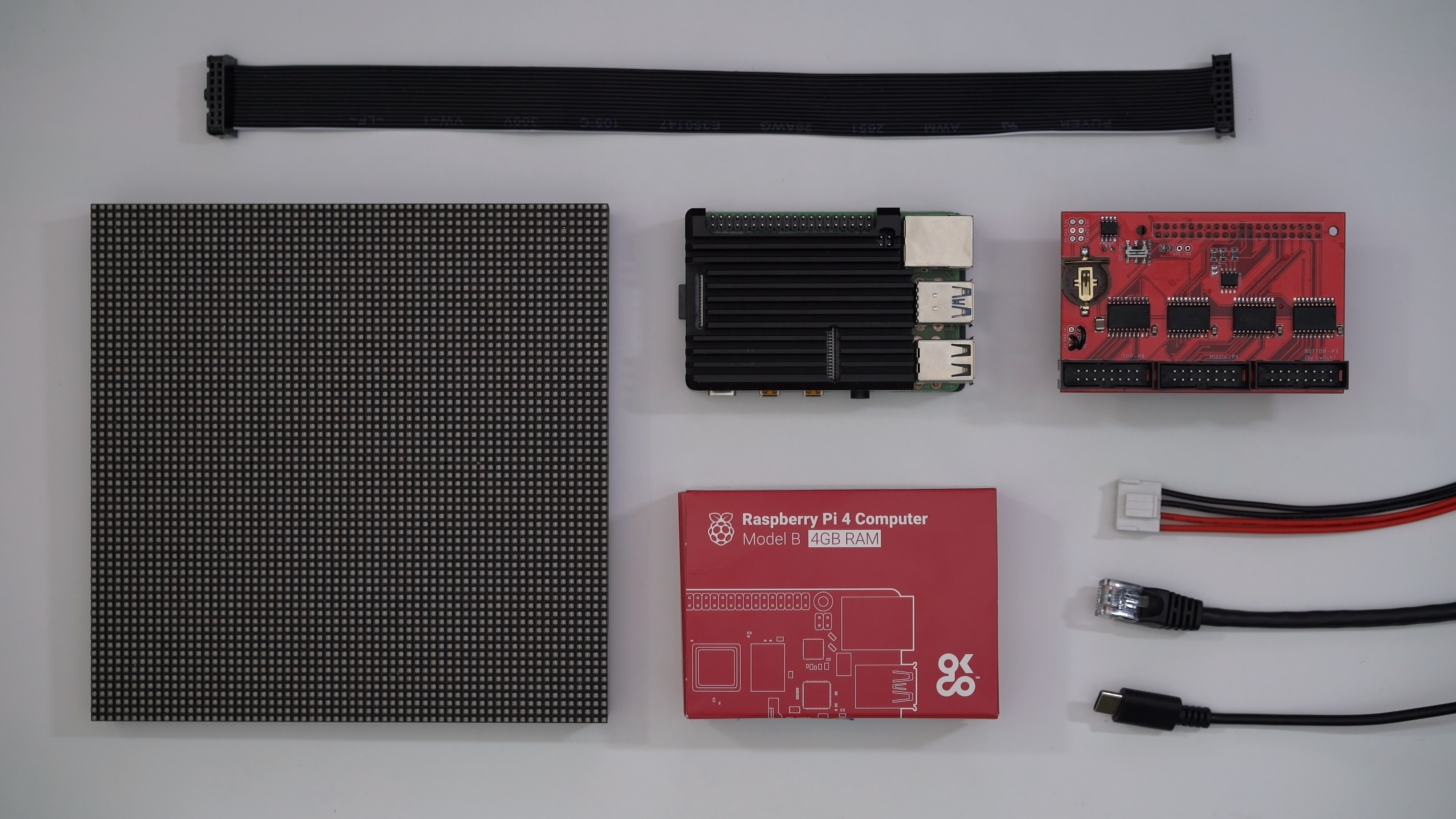
Parts
- Raspberry Pi 4 Model B
- Raspberry Pi USB-C Power Supply
- 16GB microSD Card
- Electrodragon Active-3 Breakout Board
- RGB LED Matrix Panel (64x64 - 2.5mm Pitch - 1/32 Scan)
- IDC Ribbon Cable (Hub75 / 2x8 IDC Cable)
- Power Cable (4-pin 3.96mm pitch)
- 5V Power Supply
That's my exact setup, but you can:
- Use a different panel size
- Use a different Pi (Supported Raspberry Pi versions)
- Use a different Breakout board or an Adafruit HAT/Bonnet
- Wire by hand without a breakout board (Wiring guide)
You can find these panels on:
- Adafruit - US
- Sparkfun - US
- Pimoroni - UK
- The Pi Hut - UK
- Aliexpress - China
The ribbon and power cables are usually included with the panel.
Pitch is the distance between the center of one LED and the next, usually in millimeters. A 2mm pitch is very close and is great when viewed at close range. Whereas, something like 6mm is often used with larger LEDs, better when viewed at longer range.
The scan rate is a ratio for how much of the panel is lit at a time. Generally, a higher scan rate means a faster refresh rate (1/8 is faster than 1/32).
If you're buying multiple panels for a project you should always buy extras. Also, specify in the order notes that all panels must be from the same batch. This is because:
- 📦Panels could be damaged on arrival.
- 💔The LEDs can be very fragile and easily damaged.
- 🎨A future order will come from a different batch with noticeably different colors.
Most of these panels need a 5V power supply. On average, a single 32x32 panel can draw 4A, and the 64x64 panels I use can draw 6A.
Make sure the power supply can handle the number of panels you want. I use a couple of 5V 60A switching power supplies. You can likely find these at the same stores listed above for the panels.
I recommend testing the DC voltage output with a multimeter before wiring up any panels!
Learn more about power supplies on:
Installing DietPi
First, let's flash DietPi to the microSD card. DietPi is a lightweight, non-GUI, distribution for the Raspberry Pi. This is ideal to cut CPU usage and interference with the LEDs.
- Extract the DietPi
.7zarchive to get the.imgfile - Run Etcher
- Select the DietPi
.imgfile - Select the drive of your SD card
- Click
Flash!
For WiFi configuration and troubleshooting please refer to the DietPi Getting Started guide.
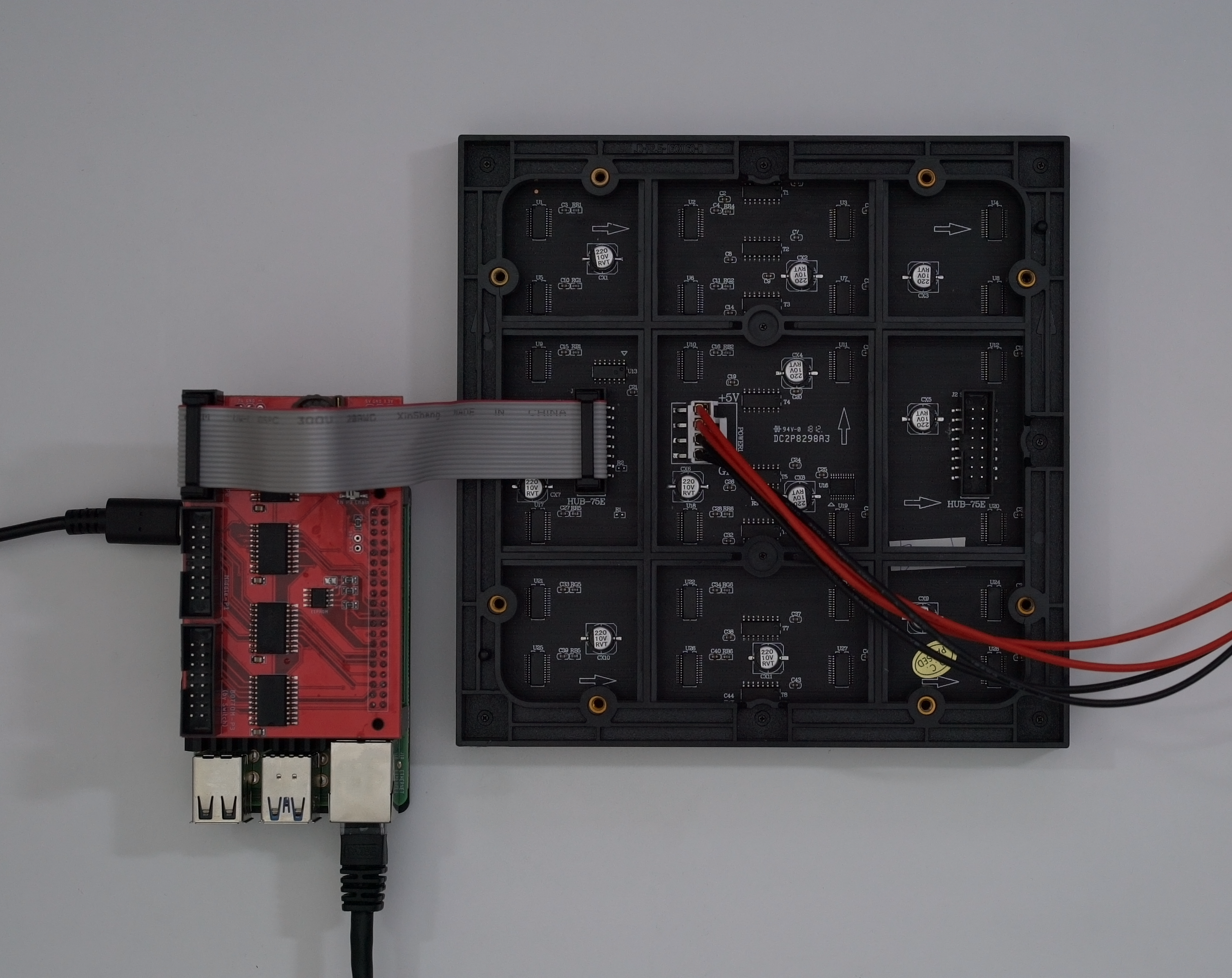
Preparing the Hardware
- Make sure the power is off while you're assembling everything
- Raspberry Pi:
- Insert the microSD card
- Add the breakout board
- Connect the ethernet cable
- Connect the USB-C power cable
- Connect the breakout board to the panel's input socket with a ribbon cable
- Connect the power cable to the panel
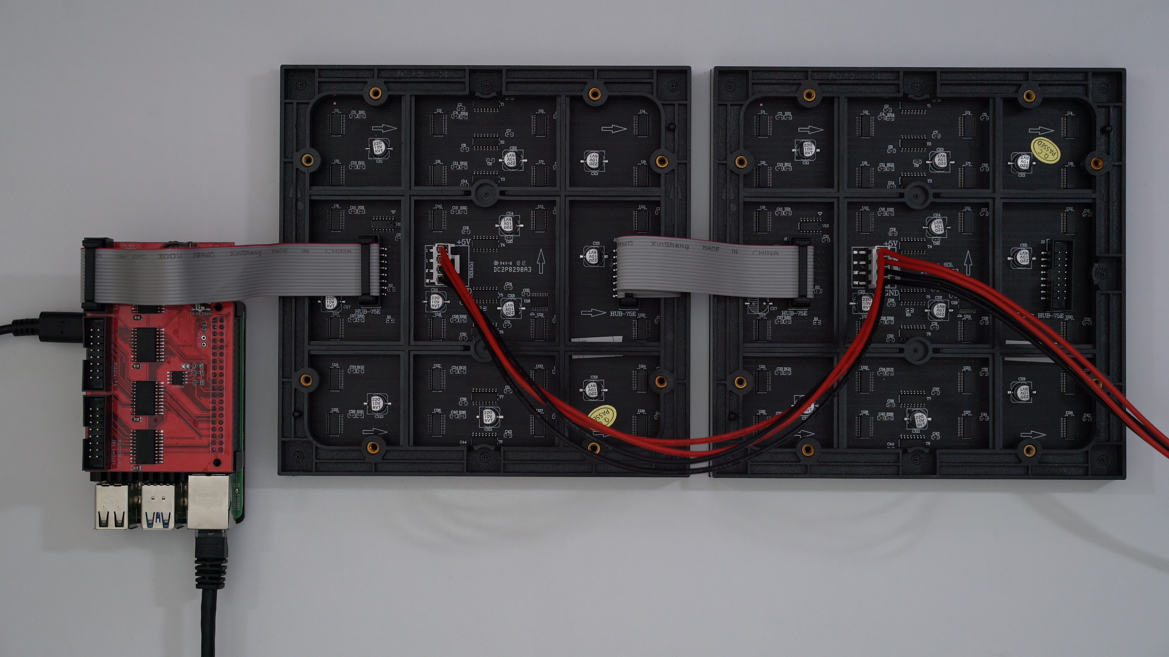
If you have a 64x64 matrix with 1:32 multiplexing, you need to supply an E-address line to it. The Electrodragon board has rearranged these points, so please pay attention to the labels on the PCB!
You can see the sockets are labeled HUB-75E on my panel's PCB. The E indicates this address line is required.
Panels will have 2 data sockets, one input, and one output. Allowing you to daisy chain panels together. Make sure you connect the breakout board to the input socket.
Most panels will have the sockets labeled input and output.
But, some panels will have arrows that point in the direction of the output. Like the image shown below.
Adding Extra Panels
You can add more panels by daisy chaining them with the ribbon cables. Connect the output socket of one panel to the input socket of the next.
Adding more panels will slow down the refresh rate. Try to use 2 or 3 parallel chains from the breakout board to achieve a faster refresh rate. Each parallel chain must contain the same number of panels.
The power cables that come with the panels often support a maximum of 2 panels. Always connect them directly to the power supply without chaining more than 2 panels together.
Chaining them would cause the current for all panels to run through the power cables, instead of the current for 2 panels. This is not safe because the cables can't handle that amount of current.
Preparing the Pi Software
ssh root@192.168.0.100First, let's open up a terminal on our dev machine and ssh into the Pi.
If you're unsure of how to find the local IP address for your Pi, check the IP Address documentation on the Raspberry Pi website.
The default DietPi login details are:
- Username:
root - Password:
dietpi
Go through the basic DietPi setup. When you reach the menu with multiple options, select Install at the bottom without additional software.
When you're in, let's get everything installed:
apt install git make build-essential

git clone --recursive https://github.com/jmswrnr/rpi-matrix-pixelpusher.git
cd rpi-matrix-pixelpusher

make
We start by installing git, make, and build-essential.
Then we clone and make the rpi-matrix-pixelpusher repo.
Right now, the matrix submodule is using an older version, while my PR is pending we will use my fork.
Running the Pi Server
Now we have everything installed on the Pi, we are able to run the PixelPusher server!
./pixel-push \
  --led-show-refresh \
  --led-rows=64 \
  --led-cols=64 \
  --led-parallel=2 \
  --led-chain=2 \
  --led-slowdown-gpio=2 \
  -u 65507
These launch options are a good starting point:
--led-show-refresh- Show refresh rate--led-rows- Number of horizontal LEDs per panel (width)--led-cols- Number of vertical LEDs per panel (height)--led-parallel- Number of chains you're running from the breakout board--led-chain- Number of daisy-chained panels--led-slowdown-gpio=<0..4>- Needed for faster Pis/slower panels. You want this value as low as possible without it looking broken.-u- Max UDP packet size. Max is65507, use the maximum that works with your network.
If you want a higher refresh rate with less color accuracy, you can lower the PWM bits: --led-pwm-bits=<1..11> default is 11.
There are plenty of options to play around with. You can tweak them to achieve a different balance of color accuracy, brightness, and refresh rate. For more info check the rpi-matrix-pixelpusher documentation and the rpi-rgb-led-matrix documentation.
Client Examples
Now the Pi is now running the PixelPusher server, we can draw to it using Node.js on our dev machine. You can find examples used in this guide on GitHub.
# Run this on your dev machine, not the Pi
git clone https://github.com/jmswrnr/canvas-led-examples
cd canvas-led-examples
Node.js Client
This example uses Node.js and node-canvas. This is a great way to render if you only need 2D rendering without a GUI or preview.
This canvas implementation doesn't support WebGL. See the Compatibility Status page for more details.
cd node
npm install
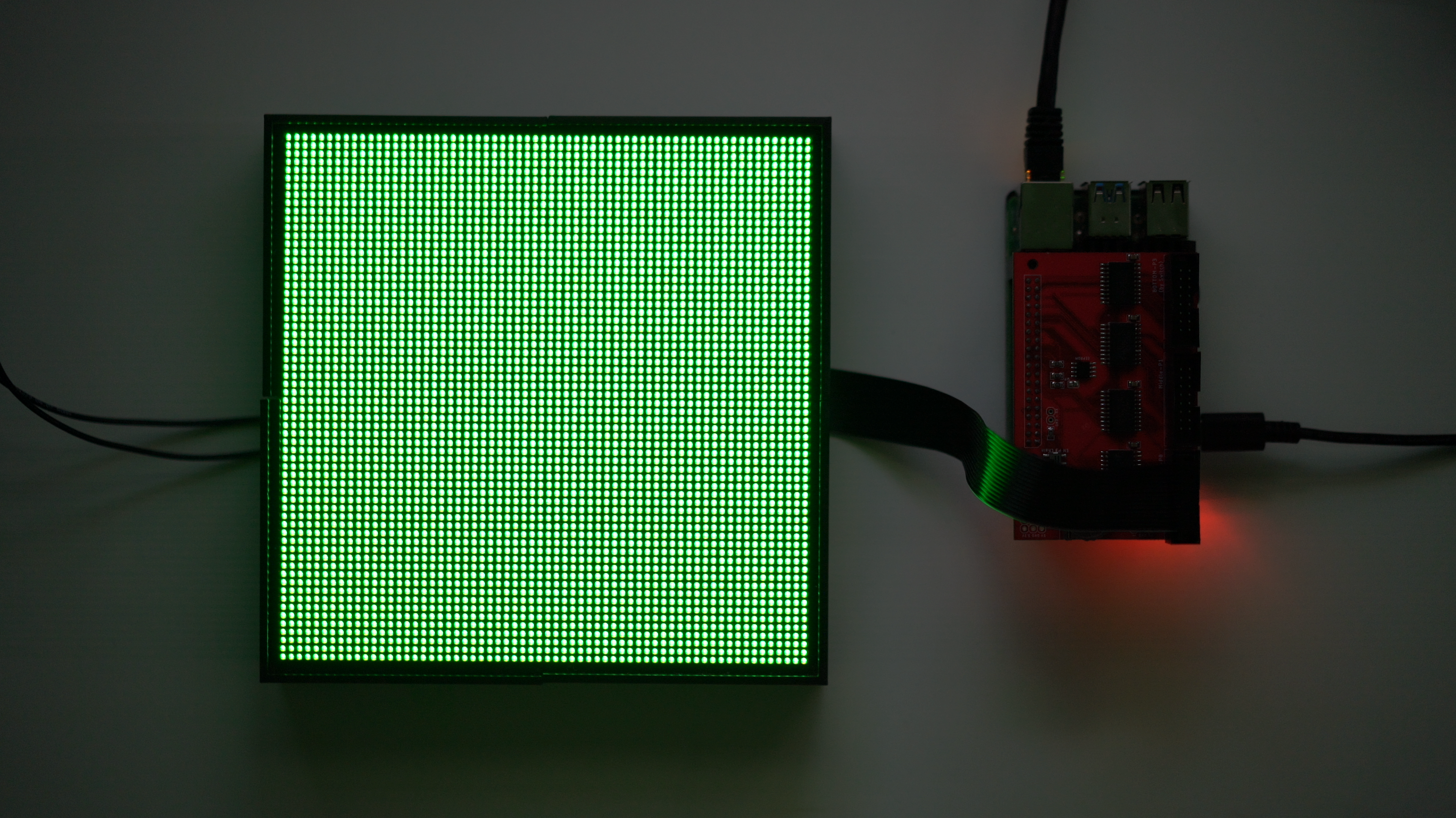
npm run startAfter running this example, you should see all your LEDs light up green!
Let's take a look into how this works:
const PixelPusher = require('node-pixel-pusher')

const service = new PixelPusher.Service()

service.on('discover', (device) => {
  createRenderer(device)
})
Using the node-pixel-pusher module, we create a Service.
This service will detect PixelPusher servers on your network, and we can handle this with the discover event.
When we discover a device, we want to create a renderer for it.
const nodeCanvas = require('canvas')

const MAX_FPS = 30

function createRenderer(device) {
  const width = device.deviceData.pixelsPerStrip
  const height = device.deviceData.numberStrips
  const canvas = nodeCanvas.createCanvas(width, height)
  const ctx = canvas.getContext('2d')

  console.log(`Creating renderer ${width}x${height} ${MAX_FPS}fps`)

  device.startRendering(() => {
    // Render
    ctx.fillStyle = 'green'
    ctx.fillRect(0, 0, width, height)

    // Get data
    const ImageData = ctx.getImageData(0, 0, width, height)

    // Send data to LEDs
    device.setRGBABuffer(ImageData.data)
  }, MAX_FPS)
}
When creating a new renderer, we first want to create a new canvas. We can get the width and height values from the device's DeviceData object.
We then use the device's startRendering method to create a render function. Limiting the FPS (frames per second) to 30.
This render function:
- Fills the canvas with green
- Gets image data from the canvas
- Updates the LED device with the image data
You can return false from the render function if you didn't make any changes. This will prevent the LEDs from being updated that frame.
The render function is also throttled based on network speed and LED refresh rate, so you don't need to worry about that.
Electron Client
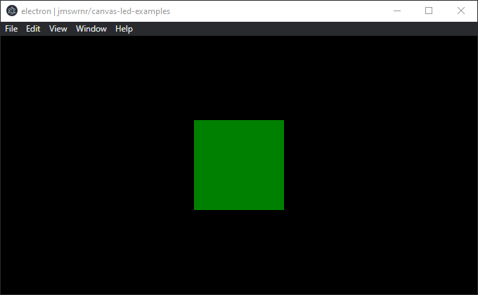
This example also renders everything green, but using Electron instead of only Node.js. This gives us Chromium performance, a GUI, and WebGL support!
cd electron
npm install
npm run start
We can now preview the render on a <canvas> in the Electron window:
const mainWindow = new BrowserWindow({
  webPreferences: {
    nodeIntegration: true,
    backgroundThrottling: false
  }
})

mainWindow.loadFile('index.html')
In the main Electron process, we create a BrowserWindow with nodeIntegration enabled. This allows us to use the node-pixel-pusher module inside the window.
We also disable backgroundThrottling so the rendering isn't throttled while the window is minimized or in the background.
function createRenderer(device) {
  const width = device.deviceData.pixelsPerStrip
  const height = device.deviceData.numberStrips
  const canvas = document.createElement('canvas')
  canvas.width = width
  canvas.height = height
  document.body.appendChild(canvas)
  const ctx = canvas.getContext('2d')

  console.log(`Creating renderer ${width}x${height} ${MAX_FPS}fps`)

  device.startRendering(() => {
    // Render
    ctx.fillStyle = 'green'
    ctx.fillRect(0, 0, width, height)

    // Get data
    const ImageData = ctx.getImageData(0, 0, width, height)

    // Send data to LEDs
    device.setRGBABuffer(ImageData.data)
  }, MAX_FPS)
}
The only difference between this and the first example is how we create the canvas.
Now our code is running inside the window's renderer process, we can create a <canvas> using document.createElement and append it to the body! Instead of using the node-canvas implementation.
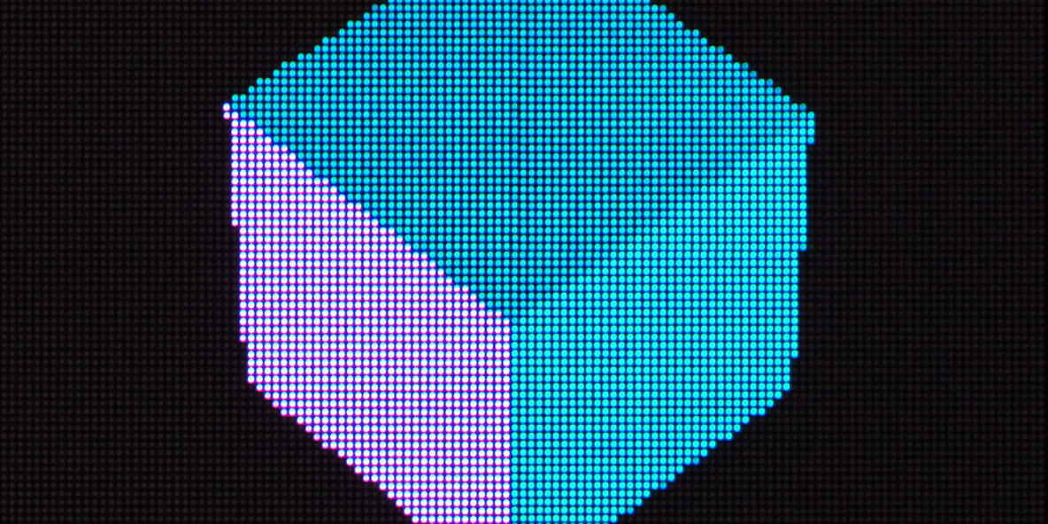
Three.js Client
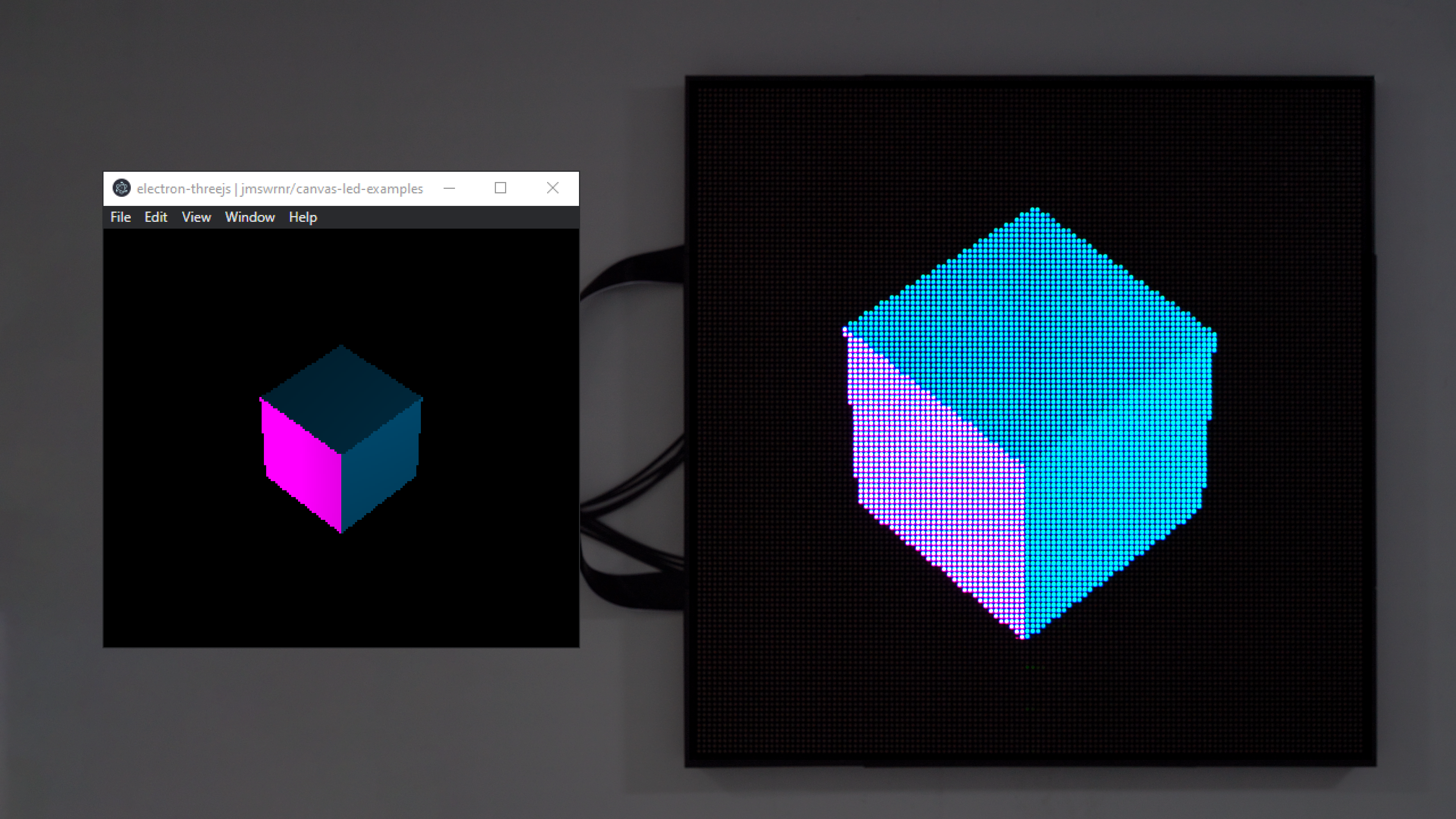
Now we're using Electron and have WebGL support, we can also render using Three.js!
cd electron-threejs
npm install
npm run start
For this example, I'm using 4 panels connected with 2 parallel chains:
Let's see how we can integrate the Three.js renderer:
const renderer = new THREE.WebGLRenderer()
document.body.appendChild(renderer.domElement)
renderer.setSize(width, height)
const offscreen = new OffscreenCanvas(width, height)
const offscreenCtx = offscreen.getContext('2d')

device.startRendering(() => {
  // Render
  renderer.render(mainScene, camera)

  // Get data
  offscreenCtx.drawImage(renderer.domElement, 0, 0)
  const ImageData = offscreenCtx.getImageData(0, 0, width, height)

  // Send data to LEDs
  device.setRGBABuffer(ImageData.data)
}, MAX_FPS)
In this example, we copy the renderer's <canvas> to an OffscreenCanvas and use a 2D context to get the image data.
This is a simple approach to render to the screen with WebGL and get the image data for the LEDs.
Here's an alternative render method if you want to dive a bit deeper:
const renderer = new THREE.WebGLRenderer()
renderer.setSize(width, height)
const target = new THREE.WebGLRenderTarget(width, height)
renderer.setRenderTarget(target)
const buffer = new Uint8Array(width * height * 4)

device.startRendering(() => {
  // Render
  renderer.render(mainScene, camera)

  // Get data
  renderer.readRenderTargetPixels(target, 0, 0, width, height, buffer)

  // Send data to LEDs
  device.setRGBABuffer(buffer)
}, MAX_FPS)
Instead of copying to an OffscreenCanvas. We can render to a WebGLRenderTarget and use readRenderTargetPixels to get the image data.
But, this doesn't render to the screen. To see a preview, you would need to render a fullscreen quad with the render target's texture.
This increases complexity but you might see better performance.
Conclusion
This can be the start of an awesome project and I hope this guide inspires you to build something with it!
To get you started, here are some of my random project ideas:
- 📈 Real-time metrics display for the office
- 🖼️ Poster/picture frame for the house
- ✨ Low-resolution magic mirror
- 🧱 Cover a wall or desktop
- 🕰️ Desktop widgets
I'd love to see anything you make with this, so please share it with me if you do! If you have any questions please let me know on Twitter or stop by my Twitch live stream where I'm often coding and answering questions!
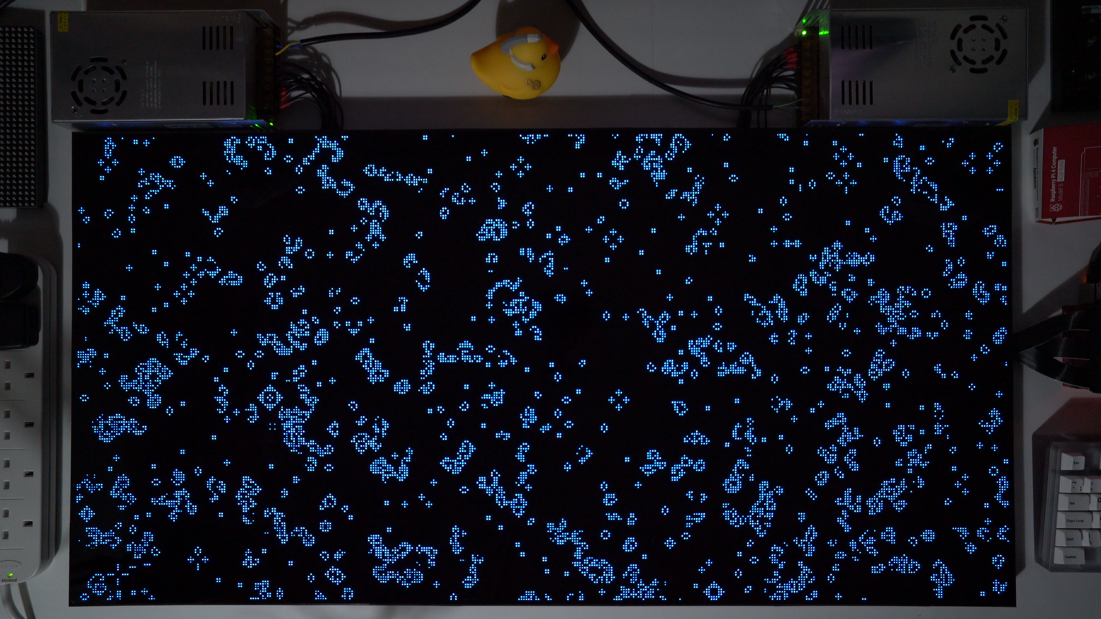
My personal projects with these panels include a Deskmat and an Interactive Twitch Display. I plan on writing separate case studies for these projects, so I won't go into detail here.
But here's Conway's Game of Life on my Deskmat: